Appendix to Steam Happens #10
Aligning Your Engine Using a $10 Digital Tachometer
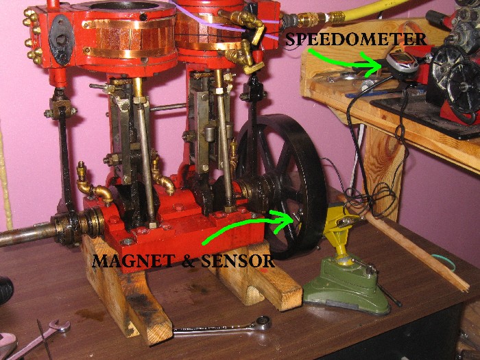
A Schwinn digital Bicycle speedometer costing less than ten dollars can be converted to a tachometer simply by selecting "miles per hour" and entering the value 2682 for the “wheel factor” (the circumference in millimeters) during the set-up procedure. Actually, most digital bike speedometers can be used as tachometers by entering the same value, 2682.
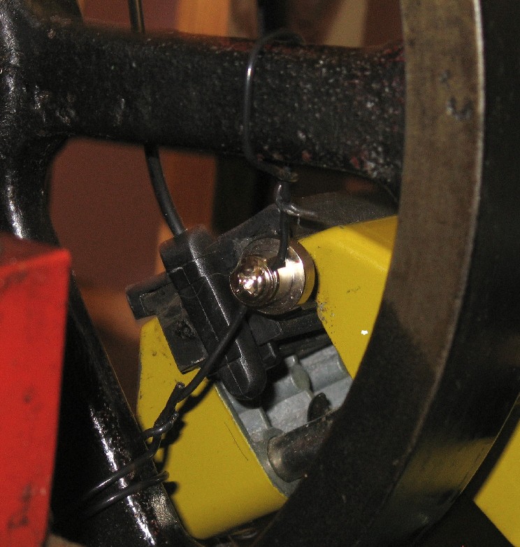
The magnet supplied with the speedometer is a silvery cylindrical fixture meant to be mounted on a spoke. As the wheel revolves, the magnet passes the sensor and the time needed for the revolution is converted to MPH or, in our case RPM. We use a length of stiff wire wrapped around the flywheel's spokes to function the magnet to be mounted. The sensor is a small black plastic device that must be located within about 1/4" of the magnet as it passes by.
In the photo below the sensor is mounted in the padded jaws of my small yellow modeling vise and the magnet has been fastened to the wire by a Phillips screw.
and from the other side
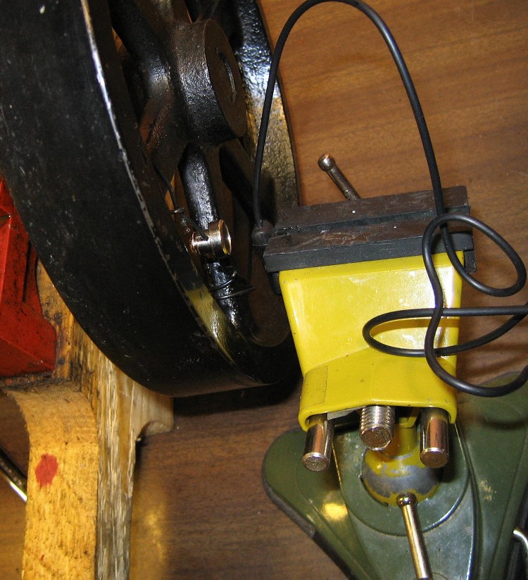
The photo below shows the magnet moved 180 degrees away from the sensor
If you can't mount the speedometer magnet to your flywheel, Radio Shack sell a pair of inexpensive rare earth magnets (64-1895) that will simply stick to the flywheel and trigger the sensor. They are strong enough to stay in place during rotation.
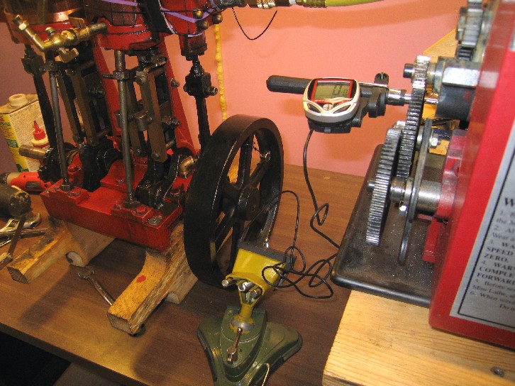
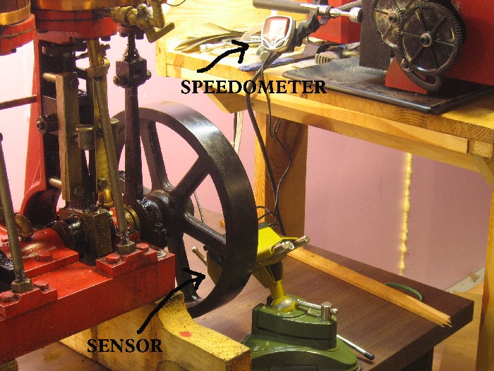
The speedometer body is positioned in a way
that it can be read
as you align the moving engine.
The cylinder cap and drain cocks are removed
from the non-powered cylinder
along with the steam transfer manifold. This reduces air flow in the non-powered
cylinder and allows the two cylinders to be adjusted independently. The
connecting stay between the two cylinders is also removed.
An air line is connected to the steam chest of the functioning cylinder, in this case the HP.
You then adjust the air flow, running the
engine so that the
compressor
is always rotating at about 200 rpm or less, thus minimizing engine vibration.
Allow the engine to run on air for at least
ten minutes to warm the bearings
and allow the functioning cylinder to cool.
We need to stabilize the running temperatures before we begin to align
the cylinder-crosshead assembly.
Once the rpms hold steady to within 2 rpm you
are ready to begin aligning the components. The bolts holding one column to the base are
loosened about 1/2 turn
and the column freed gently from the base with a rubber mallet.
The column can then be adjusted by twisting
it about the Z axis
watching the rpm meter as you manipulate. You may need to shim the column
with feeler gauge leafs to get your best performance. Work slowly! I
significantly reduced my frictional losses using this alignment process.
Below are a few short movies of the tachometer working.
Don't attempt to download these files unless you have a broadband connection as the files are between 1.3 and 3 MB insize
reading rpm before alignment at 176 rpm
engine set-up running
The aligned engine running at 189-190 rpm. Before alignment it ran at 176 rpm.