APPENDIX TO STEAM HAPPENS 5
BUILDING A CLUTCH FROM A CV JOINT
Helmut Strothjohann's boat, Vaporosa, was the first that I had seen
with a clutch mechanism. Helmut's in the right photo.
The photo was taken around 1990
CLICK ON THE IMAGE BELOW TO DOWNLOAD A MOVIE SHOWING HOW MY CLUTCH WORKS.
This is a large file. Don't download it unless you have a broadband connection or way too much time on your hands.
The clutch is disengaged in the above picture.
A diagram of a CV joint showing the typical parts. Note
that this is an outboard, Rzeppa joint.
I modified and inboard, cylindrical-type joint. The difference is in the
housing.
Here's a photo showing the difference between the above outboard Rzeppa CV
joint and the inboard joint that I used.
Note that the inboard housing is more cylindrical and has long, straight
internal grooves for sliding the entire race. The grooves run the length of the
internal housing and allow the entire race assembly and halfshaft to slide in
and out of the housing.
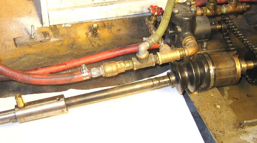
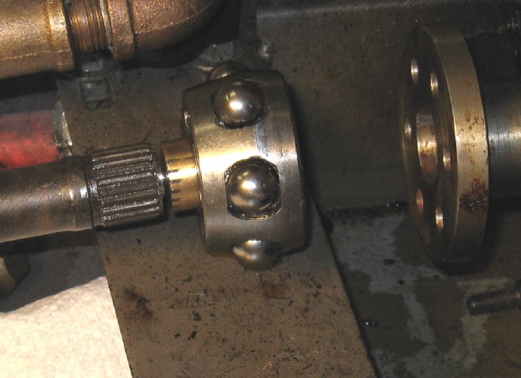
A keyed collar connects the CV halfshaft to the propshaft. Shown below, it is about 4.25 inches long and is designed to allow the halfshaft to move fore and aft causing the male spline to slide in and out of the inner race of the CV joint.
The collar position below shows the clutch disengaged. Note the brass-handled retaining pin used to hold the collar rearwards.
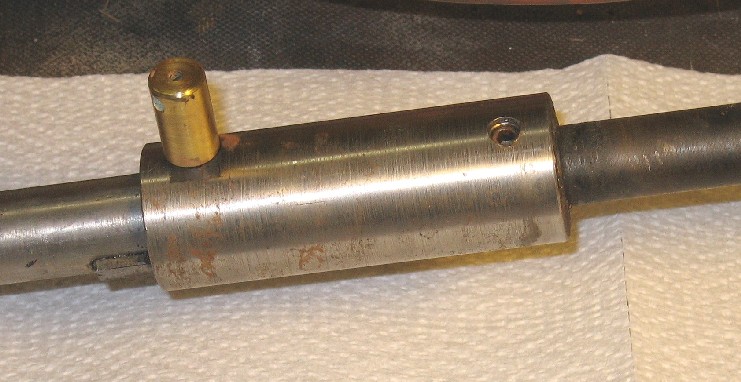
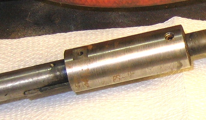
This position shows the collar position when the clutch is engaged. Note the
detent hole in the propshaft (left side).
The retaining pin fits into this hole when the clutch is disengaged.
The alignment cylinder rotates freely and keeps the CV ball race in alignment when the male
spline on the halfshaft is disengaged.
A nylon-collared nut and two spacer washers are used to adjust the backlash in
the bearings.
The photo below shows a standard nut, not a nylon-collared nut.
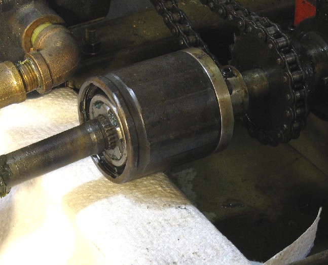
Here's a photo of the ball race in the engaged position on the halfshaft's male spline
Here's a photo of the ball race in the disengaged position on the alignment
cylinder. Unfortunately, the ball race is inserted backwards in the photos.
Still worked, though! It's correctly aligned in the boat.
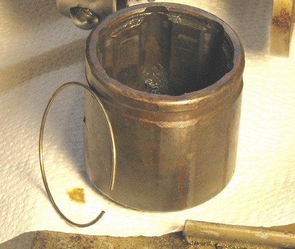
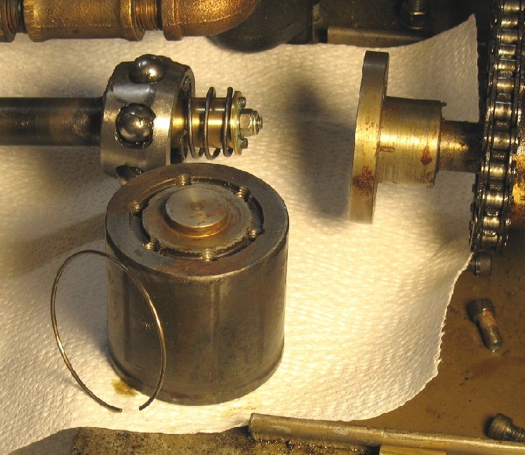
Here's a disassembled view of the alignment cylinder. Note the ball bearings
and spacer washers.
The cylinder is sized to the minor diameter of the spline and is about twice the
length of the spline.
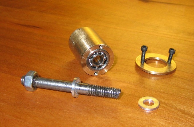
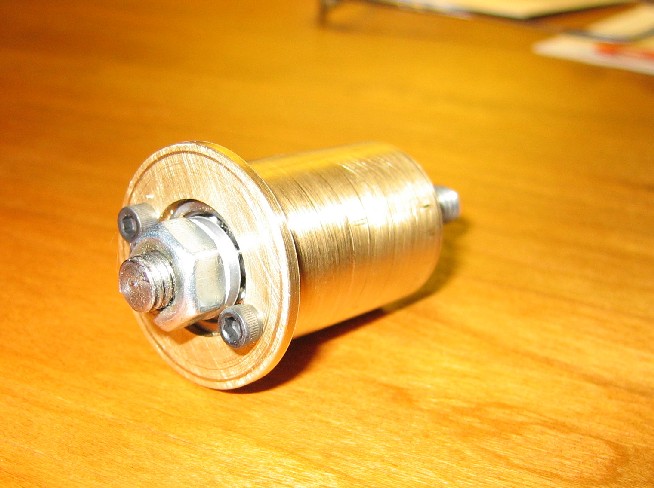
Here are front and rear shots of the assembled alignment cylinder.
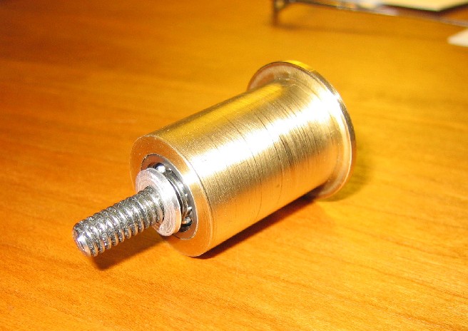
The brass spring retaining washer shown bolted to the fore end of the cylinder
by two small cap screws could have been
machined
as a single piece with the cylinder.
This retaining washer is used to retain a short, weak tensioning spring that puts about 3 lbs of
force on the disengaged half shaft.
Here's a picture of the alignment cylinder with the spring in place.
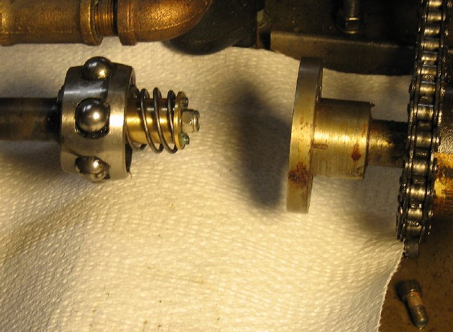
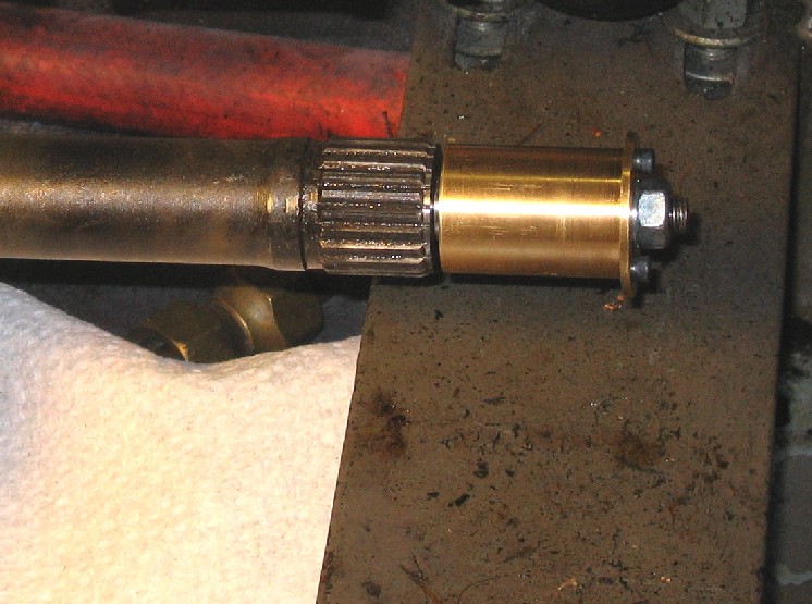
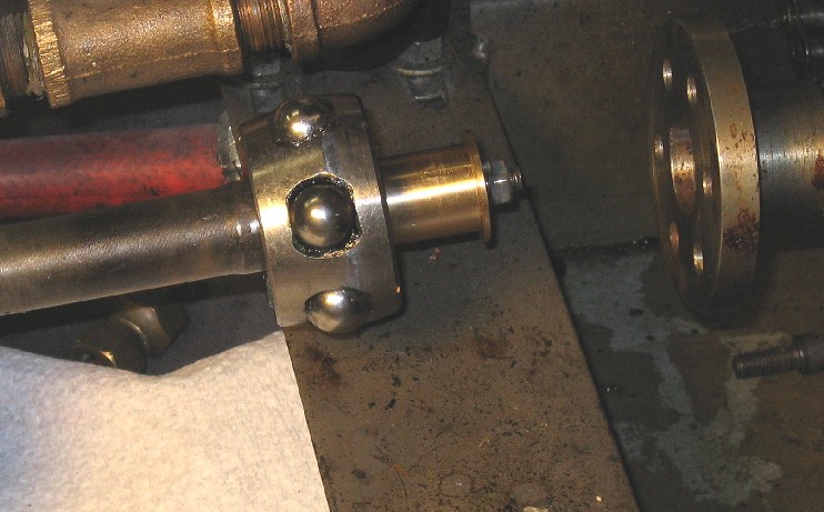
The housing was annealed and the housing's external splined shaft, which was originally designed to fit the housing into the car's transmission, was machined down to a boss the same diameter as my engine shaft (pictured below). This helps align the housing when it is bolted to the flange on the engine seen on the right of the above picture.
Below you can see the engaged clutch with the boot removed. When the
boot is in place, it is held only by the retaining clamp on the housing.
The small rear boot clamp is not used since the housing and ball race is always
turning whether or not the clutch is engaged.
See the second picture from the top.